Floor
Full Access Member
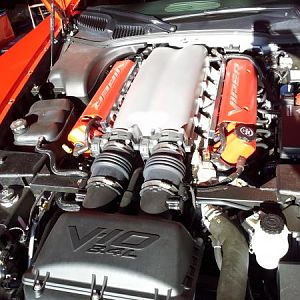
Have a look at this :

Same wire color for 1 & 7, same color for 3 & 8.
Is it safe to say they inject at the same time?
Same wire color for 1 & 7, same color for 3 & 8.
Is it safe to say they inject at the same time?