Help with AEM wideband failsafe install please

Oggers

Full Access Member
Joined
Jul 1, 2014
Messages
142
Reaction score
0
Location
Reading, uk
f01c69e0f14aa7ebb93749a894cddfa8.jpg


I've been getting together all the info I'll need to get this wired in. The story so far.
I have:
Power RED
Tach GREEN
Ground Black
thanks to this thread
http://www.vtcoa.com/forums/f7/wiring-help-please-27101/

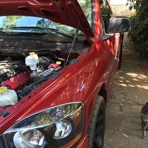
I have boost/vacuume hose thanks to this
http://www.vtcoa.com/forums/f7/paxton-almost-done-boost-gauge-38785/

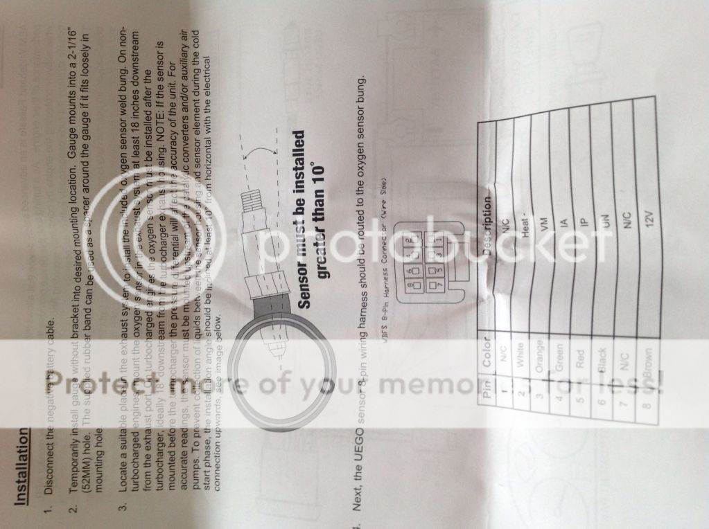
The wideband sensor will be installed near the original lambda as per instructions from AEM
20dbded463e1774b5b125be05c4ba090.jpg


What I need help with is
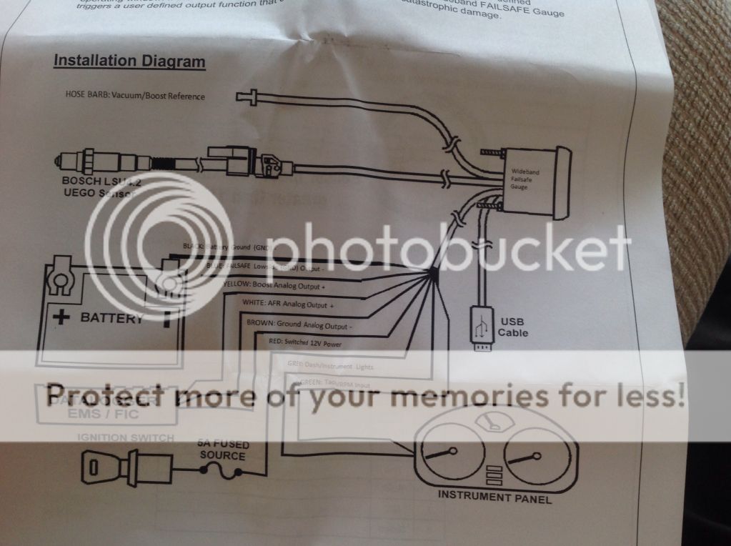
Yellow: Boost analog output?
White: afr analog output?
Brown: Ground analog output?
Grey: Dash/instrument lights?

Where is the best place to splice these wires into? On the instructions it's the datalogger ems/fic?

Will I find the correct wires down by the clutch pedal? Where I'm going to run the power from?

With the tach wire I've read that if I connect the tach wire on the failsafe to the dark blue and white to the (PCM)it will only give me 2 cylinders is that something that I need to worry about?
Pin #1 is circuit K133 dark blue/white for coil control #4

Cheers, Charlie
 
Found some more info on a s2000 forum
Black: battery ground - you can tap into your VAFC harness or attach this to a bare metal chassis point under the dash
Blue: failsafe output - wire this to your failsafe device (aftermarket ecu, warning light/alarm, etc if applicable). I did not use this output (yet) so I just capped it off.
Yellow: boost output - run to aftermarket ECU or cap if not used.
White: AFR output - run to aftermarket ECU or cap if not used.
Brown: Analog output ground - run to the same ground you used on the black wire, or cap if you aren't using the yellow or white wires. It isn't necessary to wire this to a ground of you don't use the boost/Africa outputs.
Red: 12v power - you can tap into the ignition power source on the VAFC or grab the ignition power source available in the fuse box.
Gray: instrument lights - you can grab this signal from the same area in the fuse box, it is the adjoining available prong to the ignition power source. You don't have to wire this up if you don't want to; it just dims the gauge when you turn the headlights on (nice feature).
Green: tach/RPM signal - You can grab this from the VAFC harness or tap directly off from the ECU harness. This also isn't necessary for proper operation of the gauge, but allows you to output RPM data into AEMData for awesome graphing capabilities.
 
Still on the hunt for a few answers.

The dash/instrument light wire. Can I use a wire at the back of the light switch, if so what colour do I need.

This wire is just to make the gauge dim when all the lights are on.

And the tach question any takers?

Anyone?
 
Ok I've got the gauge in its a bit ghetto at the moment as I'm on the hunt for a nice steering pod.
The boost is T'd into the boost pipe just befor it goes into the Paxton split second controller. Is that a good location?

But I'm havering a little trouble getting signal from the rpm/tach it's scotch locked into the blue and white wire on the PCM but I'm not getting any reading from the failsafe.
Is there a way of checking the signal from this wire with the engine running. Multi meter ?
 
chris had me get my tach signal from the factory JTEC tach output on C3 pin 31.. i had to go to the wreckers and rob a pin then drill a small hole in the plug to add a connector to pin 31
 
there are 3 plugs on your ecm, c3 is the top one and when you pull it apart you will see there is a blank spot marked 31 that you need to drill out and put a wire
 
Thankyou I'll have a look tomorrow when it's light. What year is your truck? does the PCM and pins change with what year the track is?

What did you use the rpm signal for?
 
there are 3 plugs on your ecm, c3 is the top one and when you pull it apart you will see there is a blank spot marked 31 that you need to drill out and put a wire

Right I've been out and had a look and found the right pin.
When I drill it out will I just be able to push my tach/rpm wire from the gauge into the hole and it will give me a good connection, or do I need to try and find a proper pin connector?

What do you run from this connection?

Cheers.
 

Latest posts

Support Us

Become A Supporting Member Today!

Click Here For Details

Back
Top