The Hellboy Update on the Ram From Hell

Ram From Hell

Full Access Member
Joined
May 25, 2006
Messages
3,022
Reaction score
0
Location
Bremerton, WA
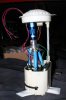
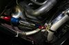
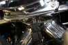
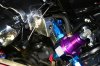
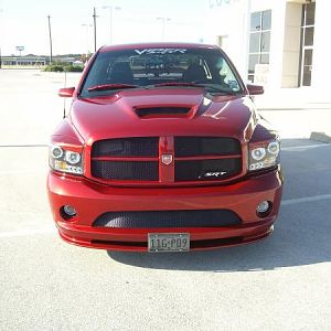
I thought it was about time that I took a few minutes to do some show and tell on the progress being made on the truck. This weekend saw a lot of progress. Enough that it could be fired off with the addition of fluids, and loading the base map into the AEM. Aside from that, it's down to gauges and some miscellaneous electrical connections (although there's plenty of that to be done).

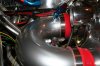
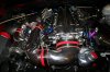
Bear in mind that this could have been done a long time ago, but doing this at a casual pace, hand polishing and sealing the bright metal stuff, waiting (and waiting, and waiting, did I mention waiting?) for eX-Metal stuff (some pieces more than once), test-fitting multiple components multiple times... You get the picture.

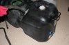
Of course there's no instruction manual for this kind of build. Just about every one of the mods has been modified (at least once). Some pieces are one-off, or DIY. I hope that I've done everything that's reasonable, and then some, to make sure that it not only works well, but lasts. There are several uses of thermal shielding and coating, including on some engine internals. I've also tried to give consideration to potential wear spots, and future access/service. It just plain takes time.

Over the course of the day I'll be posting some photos and comments of the various parts and systems, and wrap up with some photos of where things are today. So check this thread off and on today, or be efficient and wait until the end of the day to see it all at once.:D

Thanks,

-RFH

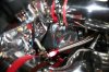
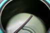
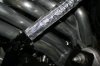
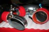
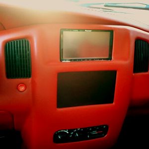
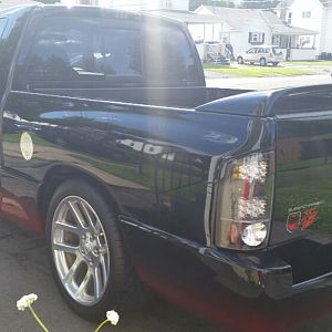
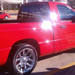
Here's a teaser pic to start this thread off.
 

Attachments

  • Reduced Teaser Closeup.JPG
    Reduced Teaser Closeup.JPG
    221.7 KB · Views: 445
Well... it's been 15 mins....... We're waiting.... :D
 
Manic said:
Well... it's been 15 mins....... We're waiting.... :D
He is shining his Bling, give him a few more minutes for the camera to adjust.:D
 
:dontknow: lets go Eric, post up the good stuff:D
 
I might as well start off with the fuel system.

I dropped the tank, and sent the fuel pump assembly off to PBJ. They replaced the single stock pump with THREE pumps in parallel, and plumbed it to a -10 fitting at the top of the assembly. I added a -8 return fitting at the back of the tank, and installed a section of hose inside the tank just past the fuel pickups. This was done in the hope that the fuel aeration will settle out before it has a chance to get to the pickups (Check out the shot of the fitting from inside the tank. I think I must have been catching a buzz from the fumes about then. :)).

From the tank, the outgoing fuel hits a high-flow fine screen Magnafuel filter (wrapped in thermal material, as are both the fuel lines AND the mid-pipe in that area), then a -10 Y-block to two -8's where it feeds the back of the fuel rails. At the front of the rails, the fuel is routed to a Magnafuel pressure regulator. The regulator is boost-referenced, and an FJO pressure sending unit and gauge provides in-cab monitoring. From the regulator, the lines go back under the manifold and to the return line on the tank. The injectors I'm starting with are flow-matched 80# units.

One fun little project this system brought about was interference between the driver's side fuel rail and the MAP sensor on the intake manifold. Note that the factory location has been threaded and plugged. The new location is underneath the intake in an unused port. I bored out a pipe nipple, and epoxied the sensor in it. Problem solved.

Then I had to do it over, because I had reinstalled the factory sensor vs. the 2-bar sensor that should have gone in the first time. Duh.

Separate power is supplied to the two additional pumps (one is powered off of the factory harness), and powered through relays controlled by the key-on power. The factory vapor/venting plumbing was all replaced, and re-routed along the frame rail to clean up the intake area.
 

Attachments

  • Reduced Modified Fuel Pump Assembly.JPG
    Reduced Modified Fuel Pump Assembly.JPG
    165.8 KB · Views: 401
  • Reduced Tank Fuel Return Fitting.JPG
    Reduced Tank Fuel Return Fitting.JPG
    173.2 KB · Views: 271
  • Reduced Inside Return Fitting.JPG
    Reduced Inside Return Fitting.JPG
    102.8 KB · Views: 264
  • Reduced In-tank Line.JPG
    Reduced In-tank Line.JPG
    129.6 KB · Views: 229
  • Reduced Fuel Filter and Heat Shielding.JPG
    Reduced Fuel Filter and Heat Shielding.JPG
    204.7 KB · Views: 280
  • Reduced Relocated MAP Sensor.JPG
    Reduced Relocated MAP Sensor.JPG
    209.5 KB · Views: 600
Forgot to add a photo of the fuel regulator...

I debated the mounting location for a couple of days, then hit on the idea of attaching directly to one of the fuel rails. Came out pretty slick, if I do say so myself.:)

Also notice in the shot that I have a gasket between the throttle body and intake. There isn't an o-ring on the intake, so I hand-cut a gasket out of the appropriate material.
 

Attachments

  • Reduced Fuel Pressure Regulator.JPG
    Reduced Fuel Pressure Regulator.JPG
    234.2 KB · Views: 2,079
Last edited:
As previously mentioned, judicious use of thermal protection was employed.

Anything near the headers/mid-pipes gets it. In addition to the fuel lines, the steering column boot was wrapped, and the undersides of the air intake and the intercooler were covered with self-stick thermal protection (but done carefully, as not to be seen from above). Not shown is the starter motor, which was also enclosed in thermal material.
 

Attachments

  • Reduced Column Bellows Cover.JPG
    Reduced Column Bellows Cover.JPG
    212 KB · Views: 94
  • Reduced Air Intake Underside.JPG
    Reduced Air Intake Underside.JPG
    265.5 KB · Views: 104
  • Reduced Intercooler Underside.JPG
    Reduced Intercooler Underside.JPG
    273.7 KB · Views: 100
Last edited:
Yellow venom 366 said:
Looking very good! Whats the difference in your "Hogan's intake manifold"? Other then the glare! LOL!

The most important difference is the vast improvement of balance in cylinder-to-cylinder air flow. Forced induction applications in particular see substantial Air/Fuel lean-out toward the front cylinders. The GEN III intake was a step backwards from the previous generation in this regard. Plus sheet metal intakes run much cooler. Also, the plenum volume was calculated specifically for my engine build.
 
Ram From Hell said:
The most important difference is the vast improvement of balance in cylinder-to-cylinder air flow. Forced induction applications in particular see substantial Air/Fuel lean-out toward the front cylinders. The GEN III intake was a step backwards from the previous generation in this regard. Plus sheet metal intakes run much cooler. Also, the plenum volume was calculated specifically for my engine build.

Thats some excellent info,your doin a killer job here! 2 thumbs up!
Any expected #'s for the done project?:burnout:
 
Moving on...

Next up is the water/methanol injection system.

I had always planned on integrating W/M to the build, but as with everything else, the mod was modified. It was going to be a simple injector triggered by the AEM system. What it ended up being is a two-stage system managed by the FJO injection controller. The first stage is injected in the air intake, where it helps cool both the incoming air and the Paxton. When the flow on that injector maxes out, the second and larger injector kicks in just ahead of the throttle body (this one's good for engines up to 1000hp, where the first stage is about 400hp-rated). Flow will be 3-D mapped to RPM and manifold pressure. My thinking here is to let the intercooler do as much cooling as possible in conjunction with the first stage, then let the second stage go when boost really comes up.

I opted to use the windshield washer reservoir as the tank, since it has a low-level indicator that will light up when it's time for more juice. I made a custom mounting plate for the pump from the Paxton intercooler support bracket that I didn't use. It would have been virtually impossible to mount that just with the supplied plate. The system is monitored in-cab for injection pressure, activation, and injector trouble conditions. A stainless in-line filter was installed to prevent issues with the injectors, so I don't expect to see that trouble light on anytime soon.
 

Attachments

  • Reduced Methanol Injection Pump.JPG
    Reduced Methanol Injection Pump.JPG
    190 KB · Views: 101
  • Reduced Injector Locations Before Installation.JPG
    Reduced Injector Locations Before Installation.JPG
    200.2 KB · Views: 90
  • Reduced Primary Methanol Injector.JPG
    Reduced Primary Methanol Injector.JPG
    228 KB · Views: 84
  • Reduced Secondary Methanol Injector Location.JPG
    Reduced Secondary Methanol Injector Location.JPG
    242.9 KB · Views: 221
Yellow venom 366 said:
Any expected #'s for the done project?:burnout:

I'm not holding my breath, but 400hp at the rear wheels would be nice.:p

Honestly, I'm not sure. However, I will tell you that the engine made about 617hp at Arrow during dyno testing. That was without the Paxton, without the Hogans intake manifold, on a reduced compression ratio, on a factory ECU, and on the original fuel injectors.:D
 
There should be a warning on this pic! Its like staring into the sun!!! LOOKS OUSTANDING!!
attachment.php
 
Ram From Hell said:
I'm not holding my breath, but 400hp at the rear wheels would be nice.:p

Honestly, I'm not sure. However, I will tell you that the engine made about 617hp at Arrow during dyno testing. That was without the Paxton, without the Hogans intake manifold, on a reduced compression ratio, on a factory ECU, and on the original fuel injectors.:D
So closer to 620 you think:D
 

Latest posts

Support Us

Become A Supporting Member Today!

Click Here For Details

Back
Top