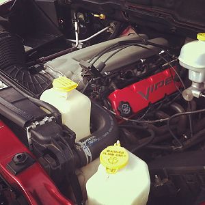
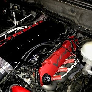
Blackviper Engine Build

blackviper said:
Thanks Larry. The two tubes going into the intake are the water inlets to the intercooler. There is an identical piece behind the intake as well. The battery was relocated using Justin's kit and the red box is the reservoir for the heat exchanger/intercooler.

:rock: I can't wait to see what she'll do:burnout:
 
A sensor is in the works. The intercooler engineer calculated based on the intercooler surface area and the size of the heat exchanger that the air inlet temperature after the S/C should be reduced by 75 to 100 degress.
 
Robert, post some pics as soon as you make some progress. Can't wait to get mine on the dyno.
 
Mine is at the pretty boring stage. Dropped the rear driveshaft yesterday. Plan on dropping the front one and the transfer case sometime this week.
 
I'm really stoked about being involved with this project:burnout: .Even though my new job is eating alot of my free time,I'm in a better position now to put more time into this build!:rock: If you look close at the pics,You'll see that the intake plate,as well as the front blower drive support bracket have been increased 3/4 inch.This in it self presented a few concerns.We are tackling each concern,One at a time.When your buiding the only Roe supercharged/intercooled built engine on the planet(literally),These things are to be expected!!:D Stay tuned for the next progress report!!!:D :D :D
 
ARRESTmeRed04 said:
just got done reading this from the start, man you are a true visionary(sp?) can't wait to see the final results
DaVinci like:rock: Just so you know I did not copy you:dontknow: Mine was red before the GTG I have witnessess:marchmellow: But the black top plate does look better. Makes you forget all the headaches Awsome Bro.:congrats: :congrats:
 
blackviper said:
Today's progress. We're definitely close.

DSCN0309.jpg


DSCN0310.jpg


DSCN0311.jpg


DSCN0312.jpg


DSCN0313.jpg


DSCN0315.jpg


DSCN0316.jpg


DSCN0318.jpg

Very well done,Looks killer!!!:rock: :congrats:
 
Here you go. The first picture is of the pulley setup. It took a while to get the right configuration.

PulleySetup.jpg


The following picture shows the 3/4 inch spacers we made up for the compressor.

CompressorSpacers.jpg


Lastly, we had to use a larger pulley on the tensioner. The pulley is actually off a Paxton kit. All of this to get a 97.5 inch Gates belt to work.

NewTensionerPulley.jpg


And here is a picture of the fuel rails.

Rail.jpg
 
Is that an extra pulley I see? that for the added height to the intake? Looks real good bro.
 
The extra pulley is used to create more belt rap to reduce belt slippage and to help take up some of the slack in the belt.
 
Damn George,looks like it's coming along nicely !!! :rock: :rock: :rock:
 
Looks great. I will be down in two weeks and stop by to take a look at it.
 

Latest posts

Support Us

Become A Supporting Member Today!

Click Here For Details

Back
Top