JMB Procharger Install

The torque limiter install is pretty simple. Mine took a little while only because the torque limiter was a bit too long (even when tightened/condensed all the way). One end of the torque limiter fits to the lower/forward header bolt on the passenger side. The other end fits to a small triangular bracket supplied in the JMB kit. The small triangular bracket fits onto the back (motor side) of the first 1/2” bracket using the 2 longer screws provided in the kit. When you install this, make sure the hole on the triangular bracket is UP.

To shorten the torque limiter I had to unscrew each end and chop about 1/8” - 1/4” off each side. If you ruin the threads, have a tap/dye set available. I only had to rethread 1 end, the other end went in fine.

Once it was short enough, install was very simple. Use the supplied hardware (bolts/washers) to mount up both ends. Quick and easy - and now all bracket pieces and hardware are used.
 

Attachments

  • IMG_1531.jpeg
    IMG_1531.jpeg
    356.3 KB · Views: 7
  • IMG_1558.jpeg
    IMG_1558.jpeg
    280.5 KB · Views: 7
  • IMG_1566.jpeg
    IMG_1566.jpeg
    283.4 KB · Views: 8
  • IMG_1567.jpeg
    IMG_1567.jpeg
    310.2 KB · Views: 9
Gawd what an ordeal! Glad you won!!
 
Oem oil temp guage is engine oil, not trans oil.
Wish i could upgrade my paxton to a procharger

Yep good catch! I mistyped - I will get that edited.

I went back and forth for a long time. Ultimately went with Procharger for power potential (one day I’ll build the motor) and because I’ve been a customer of JMB for some other stuff. Like his shop and customer service, so took my business to him. Those guys have been a much needed resource for this install. Mike is basically on speed dial at this point haha!
 
haha anytime my friend! I could always use someone to blame - easier to talk the wife into me buying expensive stuff when I blame someone else for breaking it haha
Hahaha ,, I know that feeling ,, why I’m no longer with a wife
 
Weekend update!

Received my power adder catch can from JMB this past week, so got that mounted and installed this weekend. Pretty simple install on this guy but it doesn’t come with instructions so thought I would outline the install steps.

This catch can does not recirculate air back through the intake like my old one, so a little different routing on the oil vapor lines. My last catch can had 2 ports, one running to the passenger side valve cover (VC) and one running to a hole/grommet installed in my cold air intake (CAÍ) tube. On the driver side VC, there was a hose running from driver side VC up under the intake manifold behind the throttle body. These were all 1/2” press on hoses held in place with clamps. The new catch can has 8AN fittings from the 2 ports, so I had to make some new hoses to route these from the can.

First thing I did was mount the new catch can to the heat shield provided in the JMB kit. Figure out where you want it mounted and drill 2 holes in the heat shield. Make sure you don’t obstruct the SC intake filter when mounting - also make sure you don’t mount it too high on the heat shield so your hood will close without hitting the catch can filter on top. Also make sure you don’t mount it too low so you can access the drain peacock at the bottom of the catch can. Once that is mounted, you can set the heat shield/catch can in place and start making/running your oil lines.

Since this catch can vents to atmosphere and does not recycle the air, the first thing you can do is remove the hose (if applicable on your ride) connecting to the bottom port under the intake manifold and cap that off. It is a little difficult to get to with the throttle body in place, but it’s doable. I had some PVC barb style hose connectors, so I grabbed a straight fitting, plugged one end with a rubber cap/clamp and then slid it into the rubber elbow port beneath the intake manifold (pics below).

The new catch can has 2 ports - 1 will run to your passenger side VC, and the other will run to the driver side VC. Online, JMB indicates you will need to drill/tap your VCs. I did not have to do this since my VCs already had ports on them - I just used the red hoses I had from my initial catch can and installed some barbed 8AN fittings into them to convert the line from red hose to black braided hose.

Mock up your heat shield/catch can over the passenger side wheel well and then figure out how you want to route your hoses. Get the hoses cut to length, install your AN fittings and then it’s as simple as getting them connected and tightened down. Real simple install. There are a lot of YouTube videos on how to make AN style fittings with braided/stainless hoses. Check those out and this install should go pretty fast for you. Make sure you use the appropriate aluminum wrenches as to not damage your AN fittings during tightening/install. These fittings aren’t cheap, so last thing you want to do is scratch them up with normal steel wrenches.
 

Attachments

  • IMG_1593.jpeg
    IMG_1593.jpeg
    348.1 KB · Views: 12
  • 71953107581__830780D5-759F-4BFC-85A9-1322B4DD8087.jpeg
    71953107581__830780D5-759F-4BFC-85A9-1322B4DD8087.jpeg
    262.2 KB · Views: 7
  • IMG_1597.jpeg
    IMG_1597.jpeg
    356.4 KB · Views: 8
  • IMG_1598.jpeg
    IMG_1598.jpeg
    611.6 KB · Views: 8
  • IMG_1599.jpeg
    IMG_1599.jpeg
    323.9 KB · Views: 7
  • IMG_1615.jpeg
    IMG_1615.jpeg
    469.8 KB · Views: 8
  • IMG_1617.jpeg
    IMG_1617.jpeg
    307.2 KB · Views: 8
  • IMG_1620.jpeg
    IMG_1620.jpeg
    395.3 KB · Views: 7
Weekend update!

Received my power adder catch can from JMB this past week, so got that mounted and installed this weekend. Pretty simple install on this guy but it doesn’t come with instructions so thought I would outline the install steps.

This catch can does not recirculate air back through the intake like my old one, so a little different routing on the oil vapor lines. My last catch can had 2 ports, one running to the passenger side valve cover (VC) and one running to a hole/grommet installed in my cold air intake (CAÍ) tube. On the driver side VC, there was a hose running from driver side VC up under the intake manifold behind the throttle body. These were all 1/2” press on hoses held in place with clamps. The new catch can has 8AN fittings from the 2 ports, so I had to make some new hoses to route these from the can.

First thing I did was mount the new catch can to the heat shield provided in the JMB kit. Figure out where you want it mounted and drill 2 holes in the heat shield. Make sure you don’t obstruct the SC intake filter when mounting - also make sure you don’t mount it too high on the heat shield so your hood will close without hitting the catch can filter on top. Also make sure you don’t mount it too low so you can access the drain peacock at the bottom of the catch can. Once that is mounted, you can set the heat shield/catch can in place and start making/running your oil lines.

Since this catch can vents to atmosphere and does not recycle the air, the first thing you can do is remove the hose (if applicable on your ride) connecting to the bottom port under the intake manifold and cap that off. It is a little difficult to get to with the throttle body in place, but it’s doable. I had some PVC barb style hose connectors, so I grabbed a straight fitting, plugged one end with a rubber cap/clamp and then slid it into the rubber elbow port beneath the intake manifold (pics below).

The new catch can has 2 ports - 1 will run to your passenger side VC, and the other will run to the driver side VC. Online, JMB indicates you will need to drill/tap your VCs. I did not have to do this since my VCs already had ports on them - I just used the red hoses I had from my initial catch can and installed some barbed 8AN fittings into them to convert the line from red hose to black braided hose.

Mock up your heat shield/catch can over the passenger side wheel well and then figure out how you want to route your hoses. Get the hoses cut to length, install your AN fittings and then it’s as simple as getting them connected and tightened down. Real simple install. There are a lot of YouTube videos on how to make AN style fittings with braided/stainless hoses. Check those out and this install should go pretty fast for you. Make sure you use the appropriate aluminum wrenches as to not damage your AN fittings during tightening/install. These fittings aren’t cheap, so last thing you want to do is scratch them up with normal steel wrenches.

nice looking catch can set up looks great .
Make sure you remove the plastic from the air filter before starting the engine hahahaha .. Just messing with you ! Project is moving along great ..
 
Very nice!!

your write ups are incredible. Nice and detailed so anyone can follow the bouncing ball! :cool:

Thanks Wifey! Whenever I need to pull all this stuff out to do some internal engine upgrades I am definitely going to refer back to all this! Thanks for following along - it has been a fun install!
 
nice looking catch can set up looks great .
Make sure you remove the plastic from the air filter before starting the engine hahahaha .. Just messing with you ! Project is moving along great ..

Thank you, Sir! I was definitely pleased with how it came out - looks real clean. It is a different color shade of red, but it sits far enough off to the side that it doesn't clash too hard with the bright reds. I wanted to match the inferno red/color of the truck a little closer.

Wait....you mean the plastic comes off?! I was told that was high quality heat resistant breathable plastic on that filter!!! LMAO

I will probably end up getting one of those mesh netting things to put over the filter. Just leaving it wrapped up until it's ready to fire up.

I did take your advice (I think it was yours) on wrapping up the AC hoses that run underneath the SC with some heat wrap. Anything within a few inches of that SC is wrapped up nicely and well protected.

Intercooler and new radiator should be in this week. I will be traveling this weekend so may not make a ton of progress in the next few days but hope to have it all installed and ready to fire up within the next 2 weeks. More to come!
Yes excellent progress you’re making . Great write up also ! Cant wait to see and hear about the finished project .. love it when a plan comes together !
 
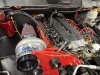
Hey friends! Couple more updates! I got the intake air temp (IAT) sensor moved, new MAP sensor, tune purchased/loaded, lower intercooler pipe installed, radiator and AC condenser back in. Ran into an issue with the dual fan setup I had, so I had to get another ordered from JMB. Details below!

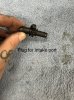
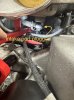
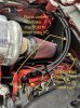
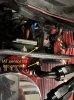
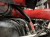
IAT sensor move: when I removed my cold air intake the IAT sensor was plugged into it (through a rubber grommet) near the driver side throttle body. This sensor needs to be moved over by the blower intake. I found out the little rubber grommet in the heat shield is actually where this sensor goes - luckily I had just enough room to plug it in there after installing the catch can. Pretty easy to knock this out - just have some 16-18AWG wire on hand to lengthen the wire and run it over behind the heat shield. I would suggest soldering these if you are able, I just used wire connectors and heat shrink (I am terrible at soldering) and getting this done up in the engine bay just wasn't going to happen for me.

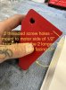
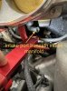
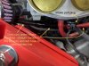
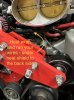
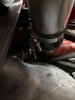
You will need to upgrade your MAP sensor. The stock SRT10s come with a 1 BAR MAP sensor, you need to upgrade to at least a 2 BAR sensor. I bought a 2 BAR sensor for a 2005 SRT4 and it fit just fine. I did call JMB to make sure before I purchased and these are what they use. I bought it from modern performance for around $40. The MAP sensor is located on the driver side intake manifold right behind the throttle body. 2 screws and you get the old out, then install the new one.

I purchased a tune from Torrie to get me running and to a dyno. Torrie will tweak the tune based on your dyno results. Torrie is well known, knows these kits well, so not too many questions to get the initial tune done. He will email it to you and you can get it loaded to your programmer. [email protected]

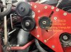
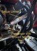
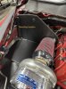
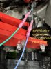
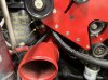
Lower intercooler pipe went on nice and easy. When you mount the blower, you would have already clocked the compressor housing and mocked up the lower intercooler pipe. The JMB kit comes with all the rubber joiners and clamps you need. The rubber joiner specific to the blower/lower intercooler has a taper - the smaller end fits to the blower and the larger end to the intercooler tube. Get everything snugged up, lined up and tighten your clamps.

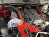
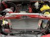
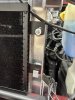
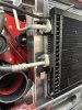
I bought a new aluminum 3 row radiator which went in just like the stock one. I did have to drill out the mounting holes a tad, they were just a hair off. Once the radiator is in you can put your lower radiator hose back in place.

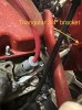
The AC condenser is modified by JMB, when you remove it you will have to send it to them. I recommend just purchasing a new one from rockauto and having it shipped to JMB. I say this because I believe I paid about $100 to ship the stock AC condenser and a brand new one is around the same price. JMB will essentially cut the AC condenser in half and weld on new mounts so you can mount it to the front of the radiator. Same issues here, the fitment was a little off so I had to drill/widen the holes - I assume this was because the aftermarket radiator was mildly mis-measured. Who knows - either way, small modifications to the mounting points and get your hardware back in and you are good to go.

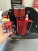
Once my new fan setup comes in I should be able to get her all finished. Really just have that, the upper intercooler pipe, the blow-off valve and the coolant overflow jug and she should be ready for a trip to the dyno!

Too many pics for single post - so pics to follow below!
 

Latest posts

Support Us

Become A Supporting Member Today!

Click Here For Details

Back
Top