theCHASE
Active Member
Hey folks - starting a thread to help any DIYer with their Procharger install. My specific application is the JMB setup. I will get some pics posted as I complete the install and answer any questions you all may have!


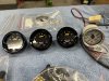
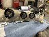
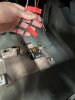
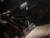
I also installed 3 more gauges to the A-pillar (boost, fuel pressure and wideband/AFR). There are enough YouTube videos out there to refer to, so I won’t go into a ton of detail on these (unless anyone has questions), but a few pics below on how I got these installed.
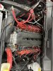
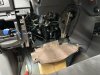
You’ll need an add-a-fuse to tap into a fuse port that provides power when you turn the key. I tapped into the cig lighter. I also used a fuse block that I mounted up underneath the steering wheel so that not all gauges were running on a single 5A fuse.
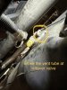
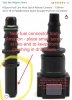
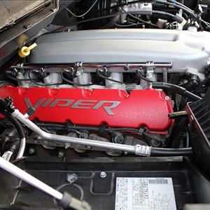
The fuel pressure sensor can tap right into the fuel rail on the passenger side - i had to buy an adaptor that fit on the schrader valve, then some other adaptors to get from the 1/8” NPT threading to the AN fittings I wanted to use.
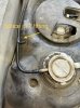
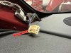
The vacuum line for the boost gauge can T into the vacuum line coming off the master cylinder. I bought some 3mm vacuum hose to replace the hose the gauge came with (mainly for color). You may have to buy some vacuum hose fittings to tap into the vacuum line, but these are cheap on amazon.
I also bought a 3D printed AEM dual sensor mount to secure the sensors near the master cylinder. This will keep the vibration and heat exposure low and prolong the life of these sensors.
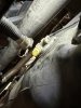
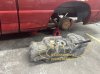
The wideband came with a bung that requires you to weld it in. I don’t have a welder, so I bought a glowshift clamp with a bung already welded in. Essentially all you have to do is drill a 13/16” hole at least 18” away from your exhaust port. I have long tube headers, so I drilled my hole at the collector of the headers. Be ready to exhaust your forearms when drilling this hole. I had to use a number of step bits to make good progress. I also cannot stress the importance of using the correct drill bit - make sure it is a COBALT (or similar hardened material) drill bit made for drilling through stainless/steel applications.
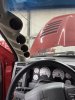
I kept the stock trans oil temp gauge mainly for budget reasons (the AEM gauge is like $200) and I also wanted the ease of using the stock plug/harness. Dodge doesn’t leave you a lot of wire excess to work with on this plug to splice in a new plug. Additionally the location of this plug makes space tight (between dash and windshield, there is only 2-3” of wire to play with).
Here for any questions on this install.
") .
.Great information..
Thanks for posting!
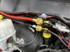
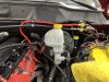
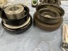
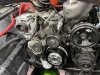
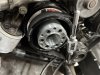
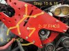
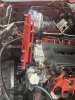
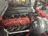
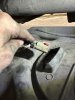
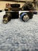
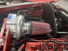
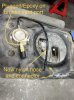
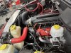
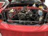
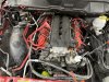
I noticed in the one pic the pro charger is extremely close to the A/C hose .. does the Pro charger cause a lot of heat ? That could damage or burn through the A/C hose .. just curious !Before you get to mounting the second bracket, which is what actually supports the SC, pay close attention to where the breather is sitting. The breather is the small air filter coming off the intake manifold just beside/below the throttle body. Installing this is done in an earlier step and its very simple with the supplied tubing and clamps in the kit, however I had to take this thing off probably 5 times because it was protruding too far and hitting the second bracket when I tried to get it installed.
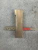
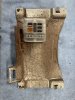
The breather needs to be short, really really short. The tube I used was no more than 2-3” long. The head of the breather CANNOT stick out further than the black spools placed on the threaded studs after you install the first bracket. If it does, you need to go shorter with your tubing. It should really sit right into the carved out slot on the first bracket. See pics below.
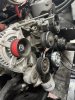
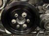
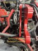
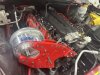
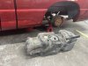
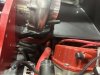
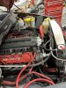
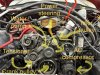
The second bracket is pretty straightforward. I won’t do a whole lot of explaining here, the pictures do it justice on how it mounts and where the hardware goes. Keep in mind these are not step-by-step instructions on the install, these are only meant to help with the instructions that JMB provides and to give a few more pictures than you will find in the instructions.
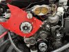
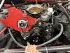
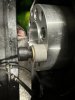
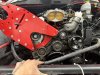
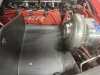
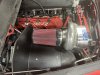
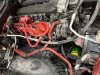
Once the 2nd bracket is in, you can finally mount the SC. You will have to clock the SC compressor housing to align with the intercooler tubing. So once you get it set in and bolted up (loosely), just know you will have to pull it back off to tighten the compressor housing bolts based on where you are routing your intercooler tubing. You will notice in the pics that I only have 1-2 bolts snug to hold the SC in place.
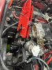
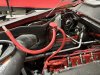
I noticed in the one pic the pro charger is extremely close to the A/C hose .. does the Pro charger cause a lot of heat ? That could damage or burn through the A/C hose .. just curious !
Ok .. better sake than sorry as the saying goesYep good question. The AC and heater hoses do run underneath the blower. I just got the heat shield mocked up last night and it provides a decent barrier. I am not sure the hoses are close enough to suffer any heat damage - then again I don’t know how hot the blower actually gets. All the hoses do tuck below both of the brackets and sit level or underneath the valve covers and the SC is propped up above the valve cover so that may create enough separation. It is hard to tell in the pictures, but there is a solid 3-4” of space between the hoses and blower itself. As a precautionary measure, I may look at getting some heat wrap for the hoses in the areas that pass right underneath the compressor housing if it looks too close.
I will keep you posted as I make it through the next couple steps in the install.
.