You are using an out of date browser. It may not display this or other websites correctly.
You should upgrade or use an alternative browser.
You should upgrade or use an alternative browser.
Trainman's Ultimate NA Build
- Thread starter Trainman
- Start date
SrtBrad
Michel Productions
- Joined
- Feb 10, 2007
- Messages
- 12,873
- Reaction score
- 17
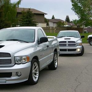
We should make this a West Coast National GTG. Someone set this up once we figure out the exact date.
SrtBrad
Michel Productions
- Joined
- Feb 10, 2007
- Messages
- 12,873
- Reaction score
- 17

SrtBrad
Michel Productions
- Joined
- Feb 10, 2007
- Messages
- 12,873
- Reaction score
- 17

SrtBrad
Michel Productions
- Joined
- Feb 10, 2007
- Messages
- 12,873
- Reaction score
- 17

These are the shots of the roll cage being installed in the truck by Bill Hickok Race Cars of California City. He will also be doing the entire rear suspension, eliminating the stock leaf springs and QA1 shocks and replacing with full Ladder Bars and Coilovers. About 3-4 weeks away. Also my CalTracs will be for sale shortly....
Still waiting for the block to be returned to Exotic Engines. There was not enough material in the block to bore out for roller bearings for the cam, so we will run a standard flat bearing for the cam. Once the block is returned it will be about 3-4 weeks to completion. Planning on SRTBrad to film the start up on the engine dyno and Chris Jensen to be there to do the breakin and tune on the dyno.
Still waiting for the block to be returned to Exotic Engines. There was not enough material in the block to bore out for roller bearings for the cam, so we will run a standard flat bearing for the cam. Once the block is returned it will be about 3-4 weeks to completion. Planning on SRTBrad to film the start up on the engine dyno and Chris Jensen to be there to do the breakin and tune on the dyno.
Last edited:
fastestbrickonearth
Full Access Member
Looking good. Gonna be hard to paint
The side bar will be removable for street use. The roll bar is tucked so tight that it is nearly invisible when the doors are shut.
Dom426
Full Access Member
Almost identical to my first cage.
Almost identical to my first cage.
How are things going with your truck Dom?
Dom426
Full Access Member
How are things going with your truck Dom?
Good it's coming together
SrtBrad
Michel Productions
- Joined
- Feb 10, 2007
- Messages
- 12,873
- Reaction score
- 17
Couple more pics:

Piston - Gen 4 top configuration with valve pockets, lateral gas ports, small dish pocket to maintain our compression target.
Piston - Gen 4 top configuration with valve pockets, lateral gas ports, small dish pocket to maintain our compression target.
Last edited:
SrtBrad
Michel Productions
- Joined
- Feb 10, 2007
- Messages
- 12,873
- Reaction score
- 17

Valve Cover Rail - This is your new valve cover. If you look at the rail, they have placed the sheet metal shell inside the rail which has compounded the clearance problem. CNC spacers will cure the problem. We have made a set prior for another project but we wanted to go back and tune up the design and reduce the overall height.
Last edited:
SrtBrad
Michel Productions
- Joined
- Feb 10, 2007
- Messages
- 12,873
- Reaction score
- 17

Valve Cover 3D Model - The white portion in the photo below the valve cover mock-up is a 3D plastic model that represents the final CNC spacer program that will be cut in aluminum. This is required to gain clearance between the valve cover and the rockers. (see next photo)
Last edited:
Got this today from Kevin, explains the 3 above pictures. I'm not sure if any coating is being considered.
Hello Jerry,
I spoke to Jaime this morning. The block is in the machine for align bore and hone. He will complete that process today. Then he has to break down from the machine, disassemble and clean the block for install of the cam bearings (cam tunnel is already cut).
The photos I have attached show:
Piston - Gen 4 top configuration with valve pockets, lateral gas ports, small dish pocket to maintain our compression target.
Valve Cover 3D Model - The white portion in the photo below the valve cover mock-up is a 3D plastic model that represents the final CNC spacer program that will be cut in aluminum. This is required to gain clearance between the valve cover and the rockers. (see next photo)
Valve Cover Rail - This is your new valve cover. If you look at the rail, they have placed the sheet metal shell inside the rail which has compounded the clearance problem. CNC spacers will cure the problem. We have made a set prior for another project but we wanted to go back and tune up the design and reduce the overall height.
Once I receive the block, we will finish hone the cylinders and check the deck relationship to the liners. Its common that we will have to make one finish cut on the deck after all of the other machine work is complete. After that we are starting to assemble. I think its a little bit early to start making schedules for the dyno. Let me get the block back in hand first.
Regards,
Kevin Singleton
SrtBrad
Michel Productions
- Joined
- Feb 10, 2007
- Messages
- 12,873
- Reaction score
- 17
Coated Pistons:

SrtBrad
Michel Productions
- Joined
- Feb 10, 2007
- Messages
- 12,873
- Reaction score
- 17

SrtBrad
Michel Productions
- Joined
- Feb 10, 2007
- Messages
- 12,873
- Reaction score
- 17
Cam bearings?

Support Us
Become A Supporting Member Today!